Hello readers, I hope you all are doing great. In our previous tutorial, we discussed the implementation of pulse width modulation (PWM) in Raspberry Pi Pico using the MicroPyton programming example. We also implemented the LED brightness control program to demonstrate an application of the pulse width modulation technique.
In this tutorial, we are going to implement another application of pulse width modulation technique which is ‘Direction and position control of a servo motor’ with Raspberry Pi Pico module and MicroPython programming language.
Later in this tutorial, we will also discuss how to control the position of a servo motor with push buttons (to be used as control inputs) and also to use LEDs for indication purposes.
What is Servo Motor?
Before interfacing the servo motor with the Raspberry Pi Pico module, let’s first understand the behavior of a servo motor and how it is different from a DC electric motor.
There are several applications for electric motors in which the motor must only rotate at a specific angle. We need a special type of motor with a special arrangement that causes the motor to rotate at a specific angle for a given electric signal (input) in such applications, or we can call it an angular precision motor. The Servo motor is used in these types of applications.
A servo motor is a low-cost, high-power output device that can only rotate 180 degrees (90 degrees in each direction) and can control the angle of rotation anywhere within that 180-degree range.
Fig. 1 Servo motor
Technically speaking, a servo motor is a linear or rotary actuator that can control acceleration, linear or angular position, and velocity with precision. It consists of a motor and a position feedback sensor. It also requires a sophisticated controller, which is often a dedicated module designed specifically for use with servo motors.
The main feature of using a servo motor is that it has angular precision, which makes the motor capable of rotating as far as we want it to before stopping and waiting for the next input signal from the microcontroller (or Raspberry Pi Pico in this project). Unlike a standard DC electric motor, the servo motor starts turning as soon as the power supply is applied to it and continues to rotate until the power is turned off. On the other hand, we cannot restrict the rotational progress of the DC motor, but we can control its speed of rotation and turn it on and off or we can say that the DC motor does not have angular precision. Small servo motors are available there in numerous Arduino launcher kits (beginners) since they are simple to use in small electronic projects and applications.
A servo motor is mostly used in obstacle detector/avoidance robots and robotic arms.
Software and Hardware Components Required
- Raspberry Pi Pico Module
- Latest version of Python
- Latest version of Thonny IDE should be installed on your system
- MicroPython setup installed in Raspberry Pi Pico
- Breadboard
- LED
- Resistor (330 ohm)
- USB cable
We have already published tutorials on how to download and install the above mentioned software components.
Follow the given link for a detailed study of Raspberry Pi Pico: https://www.theengineeringprojects.com/2022/04/getting-started-with-raspberry-pi-pico.html
Controlling servo motor with Raspberry Pi Pico
A servo motor is controlled by sending a PWM or pulse width modulated signal. A servo motor can only turn for a total of 180 degree movement (90 degree in either direction).
Pulse width modulation technique is used to control the amount of power delivered to the load for a particular time. The pulse width modulated signal sent to the motor specifies the position of the shaft, and to turn the rotor into a desired position depending on the duration of the pulse sent through the control wire.
The major factors affecting the behavior of pulse width modulation are frequency and duty cycle. Frequency defines the number of cycles per second or it is the reciprocal of total time ‘T’.
Frequency = 1/ T
Where, T= ON time + Off time
The duty cycle determines the time for which the output pulse from the Raspberry Pi Pico is high.
Duty Cycle = ON time/ T
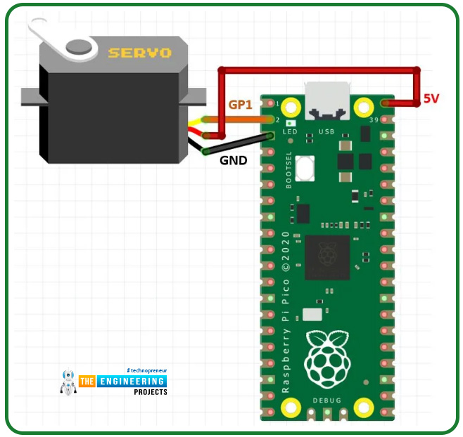
Interfacing Servo Motor with Raspberry Pi Pico module
Fig. Interfacing servo motor with raspberry pi pico
Connections:
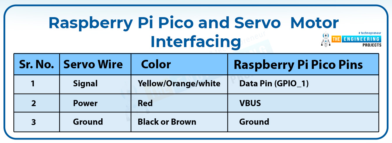
Servo motor consists of three wires; red, brown and yellow. Two wires are for VCC and ground and the third one is the data or control pin. The servo motor we are using operates at 5V dc supply so the red wire of the motor is connected to the VBUS pin of raspberry Pi Pico board. The interfacing of servo motor with raspberry Pi Pico module is shown in Table1.
Table 1 Raspberry Pi Pico and servo motor interfacing
Programming Raspberry Pi Pico with MicroPython
To program Raspberry Pi Pico board there are various development environments available (like uPyCraft IDE, Visual Studio Code, Thonny IDE ect.) and multiple programming languages as well.
In this tutorial, we are going to use Thonny IDE to program the Raspberry Pi Pico board.
Installing Thonny IDE for Raspberry Pi Pico Programming:
We have already published a tutorial on installing Thonny IDe for Raspberry Pi Pico Programming on our website. Follow the given link to install the IDE: https://www.theengineeringprojects.com/2022/04/installing-thonny-ide-for-raspberry-pi-pico-programming.html
Steps to write a program for LED brightness conrtol are:
- Open the Thonny IDE once it is successfully installed.
- Select “for all users” option.
- Connect the Raspberry Pi Pico development board with your system (laptop or desktop).
- To create a new project; go to Files >> New.
Fig. 4 New Project
- Connect the Raspberry Pi Pico board with laptop/desktop using USB cable.
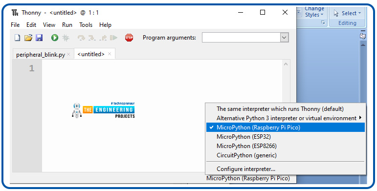
- Click on the ‘MicoPython(Raspberry Pi Pico)’ option from lower right corner in-order to select the interpreter for raspberry Pi Pico programming using MicroPython programming language. We already selected the one from lower right corner menu from the Thonny IDE window.
Fig. 5 Select Interpreter
- Select interpreter ‘MicroPython (Raspberry Pi Pico)’ for Raspberry Pi Pico programming.
Image: 6 MicroPython for raspberry Pi Pico programming
- You should see this MicroPython Version details in Shell section (to ensure that Thonny is ready to program your Raspberry Pi Pico board) as shown below:
Image: 7 Ready to program
Writing the MicroPython program for servo motor
- The first task is importing the library file necessary for servo motor interfacing and PWM implementation to control the direction of rotation.
- So here we are importing two libraries from machine i.e., ‘Pin’ and ‘PWM’ to access the GPIO pins and implement pulse width modulation respectively. The third library is ‘time’ to add delay if required.
Fig. 8 Importing libraries
- Next we are defining a ‘pwm’ object where we are configuring the GPIO_1 as PWM pin.
Fig. 9 object declaration
- Another important factor in PWM programming is the modulation frequency. We are setting the modulation frequency at 50 Hz.
Fig. 10 PWM frequency
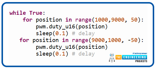
- The position of a servo motor can vary from 0 to 180 degrees. Here the servo motor position is represented in microseconds where 1000 to 9000us are representing 0 to 180 degree angular position.
Fig. 11 Changing angular position continuously
Save and test the program
-
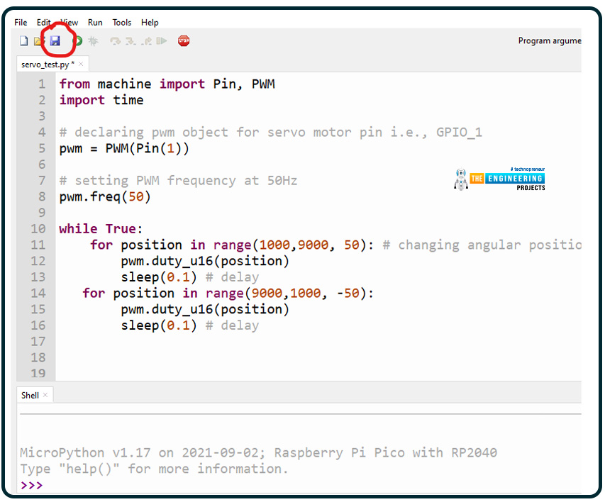
- Click on the ‘save’ icon to save the servo motor interfacing program.
Fig. 13 Save the program
- After clicking on the ‘Save’ icon, an option ‘Where to save to?’ will pop-up. You can select any of the ‘Raspberry Pi Pico’ option.
Fig. 14 Save the program
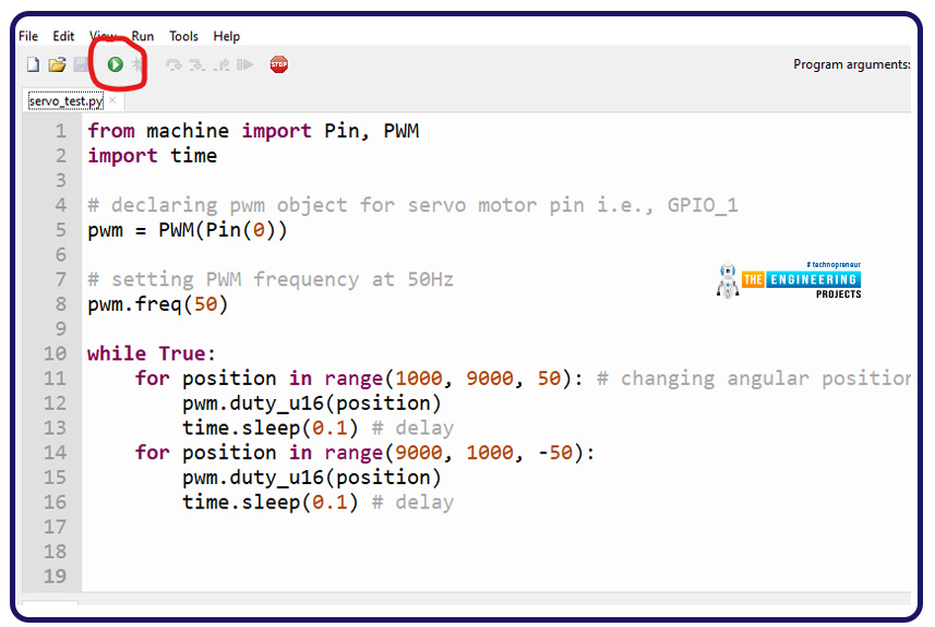
- Run the program once it is successfully saved and compiled without any bug.
Fig. 15 Run the saved program
MicroPython Code
from machine import Pin, PWM
import time
# declaring pwm object for servo motor pin i.e., GPIO_1
pwm = PWM(Pin(0))
# setting PWM frequency at 50Hz
pwm.freq(50)
while True:
for position in range(1000, 9000, 50): # changing angular position
pwm.duty_u16(position)
time.sleep(0.1) # delay
for position in range(9000, 1000, -50):
pwm.duty_u16(position)
time.sleep(0.1) # delay
Result
Fig. 16 Raspberry Pi Pico and servo motor
That’s all about interfacing and controlling a servo motor with Raspberry Pi Pico module and pulse width modulation.
So far in raspberry Pi Pico programming series, we discussed and demonstrated the interfacing of output devices with raspberry Pi Pico board.
Now let’s take another example, where we are going to control the direction of rotation of a servo motor using push buttons which are acting as control inputs and we are also using LEDs (outputs) as indicators for various positions.
Push Buttons as Control Inputs with Raspberry Pi Pico
GPIO stands for General Purpose Input Output which means a GPIO pin can be configured both either as an input or an output pin. In raspberry Pi Pico (RP2040) module we have 30 GPIO pins and hence any of them can be used either as input or output pin.
Push button is used as an input component to trigger some event or an interrupt in microcontrollers. So here in this example, we are using some push button as control inputs to control the direction of rotation in a servo motor.
Push button operates in two logic states, Digital High and Digital Low. A push button can be connected with raspberry Pi Pico either in pull-up or in pull-down mode. In pull-down mode, when the button is presses the GPIO input will be in logic high and otherwise the input will be logic zero. On the other hand in pull-up mode the GPIO input will be in logic low state when the button is pressed and vice versa.
Hardware Components required:
- Push buttons
- Resistor (10K)
Interfacing push button with Raspberry Pi Pico
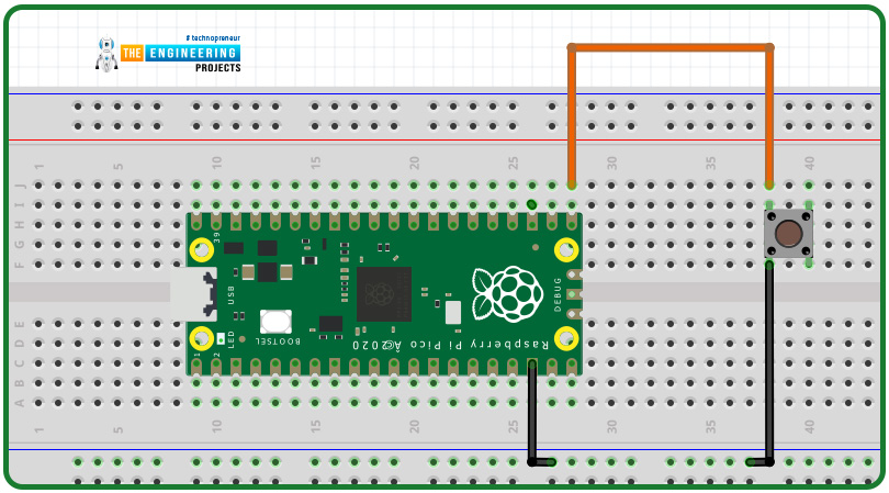
A schematic is attached below representing the interfacing of a push button with raspberry pi Pico:
Fig. 17 Push button interfacing
MicroPython Program
Most of the programming instructions will remain similar to the previous example with some additional instruction to interface LEDs and Push buttons and assigning their respective task.
- Initially, we are declaring some led objects assigning various ‘output’ pins for LED interfacing.
Fig. 18 led object declaration
- So far, we were configuring raspberry Pi Pico’s GPIO pins as output pins. Now, we will declare some ‘button_x’ objects where we will be configuring GPIO pins as input. Here we are declaring three push button objects.
Fig. 19 Push button object Declaration
- We are defining some variables to store the status of push buttons.
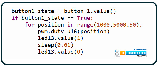
- Some conditional statements are used to change the position of the servo motor. The first push button is responsible for changing the shaft position for 0 to 90 degrees (1000 to 5000 microseconds) and the LED represented by object ‘led13’ will start to blink as an indicator.
Fig. 20 Push Button 1
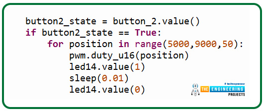
- The second push button will make the servo motor shaft to rotate from 90 to 180 degrees.
Fig. 21 Push button 2
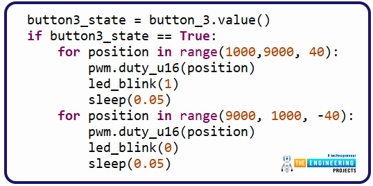
- The third push button will make the motor shaft to move from 0 to 180 degree back and forth and all the LEDs will along with the shaft movement in respective directions.
Fig. 22 Push button 3
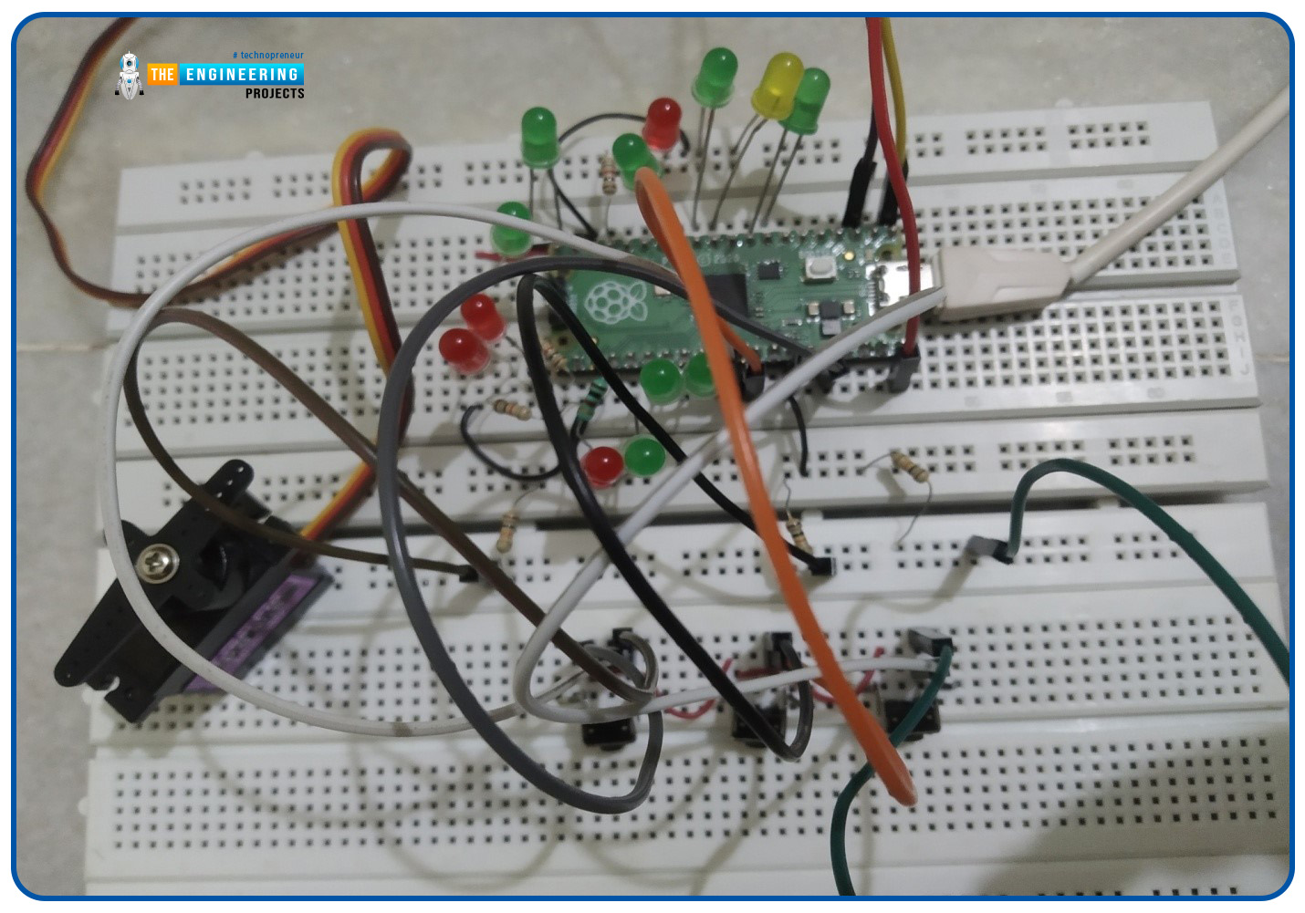
Fig. 23 Interfacing push button, servo motor and LEDs with Pico board
Fig. 24
MicroPython Code
from time import sleep
from machine import Pin, PWM
# declaring pwm object for servo motor
pwm = PWM(Pin(0)) # PWM pin for Servo motor
# declaring led object
led1 = Pin(5, Pin.OUT)
led2 = Pin(6, Pin.OUT)
led3 = Pin(8, Pin.OUT)
led4 = Pin(9, Pin.OUT)
led5 = Pin(10, Pin.OUT)
led6 = Pin(13, Pin.OUT)
led7 = Pin(14, Pin.OUT)
led8 = Pin(15, Pin.OUT)
led9 = Pin(15, Pin.OUT)
led10 = Pin(16, Pin.OUT)
led11 = Pin(17, Pin.OUT)
led12 = Pin(18, Pin.OUT)
led13 = Pin(19, Pin.OUT)
led14 = Pin(20, Pin.OUT)
led15 = Pin(21, Pin.OUT)
led16 = Pin(22, Pin.OUT)
# object declaration for push buttons
button_1 = Pin(26, Pin.IN)
button_2 = Pin(27, Pin.IN)
button_3 = Pin(28, Pin.IN)
pwm.freq(50) # set PWM frequency for servo motor
def led_blink (x):
led1.value(x)
led2.value(x)
led3.value(x)
led4.value(x)
led5.value(x)
led6.value(x)
led7.value(x)
led8.value(x)
led9.value(x)
led10.value(x)
led11.value(x)
led12.value(x)
led13.value(x)
led14.value(x)
led15.value(x)
while True:
button1_state = button_1.value()
if button1_state == True:
for position in range(1000,5000,50):
pwm.duty_u16(position)
led13.value(1)
sleep(0.01)
led13.value(0)
button2_state = button_2.value()
if button2_state == True:
for position in range(5000,9000,50):
pwm.duty_u16(position)
led14.value(1)
sleep(0.01)
led14.value(0)
button3_state = button_3.value()
if button3_state == True:
for position in range(1000,9000, 40):
pwm.duty_u16(position)
led_blink(1)
sleep(0.05)
for position in range(9000, 1000, -40):
pwm.duty_u16(position)
led_blink(0)
sleep(0.05)
Results
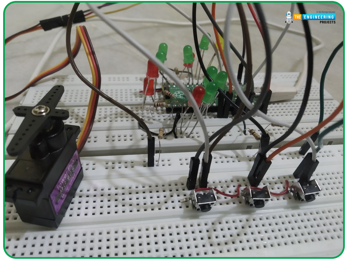
The results observed are attached below. In the image attached below, we can see the difference in the servo motor’s shaft position when compared with the previous image (off state).
Fig. 25 Servo motor control with push buttons
Conclusion
In this tutorial, we implemented another application of Pulse width modulation technique with Raspberry Pi Pico module and MicroPython Programming language. We also learn how to use Raspberry Pi Pico’s GPIO pins to receive input from peripheral devices.
So, this concludes the tutorial. We hope you found this of some help and also hope to see you soon with a new tutorial on raspberry Pi Pico programming series.
JLCPCB – Prototype 10 PCBs for $2 (For Any Color)
China’s Largest PCB Prototype Enterprise, 600,000+ Customers & 10,000+ Online Orders Daily
How to Get PCB Cash Coupon from JLCPCB: https://bit.ly/2GMCH9w
The post Interfacing Servo Motor with Raspberry Pi Pico using MicroPython appeared first on The Engineering Projects.








No comments:
Post a Comment