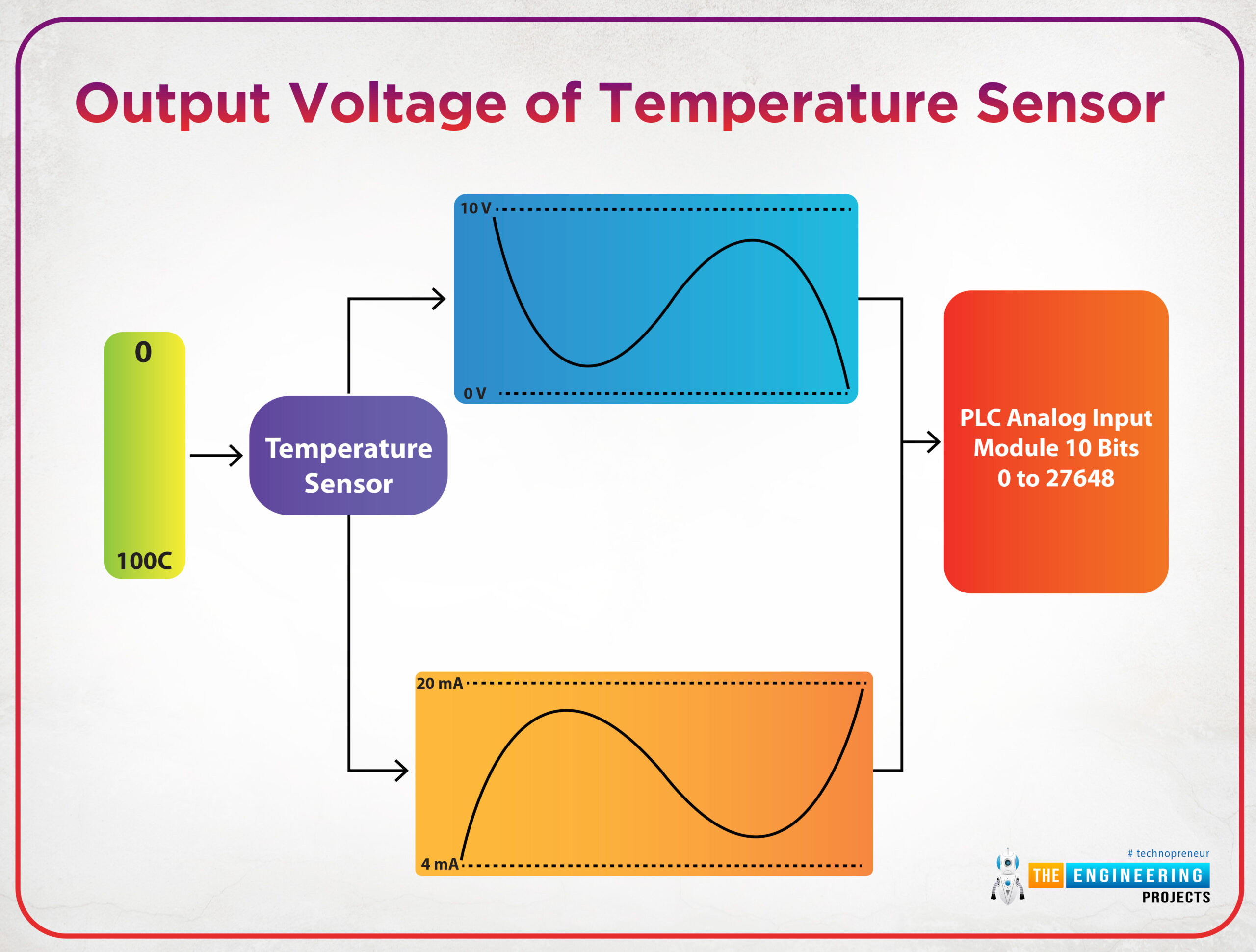
In computer systems, plc, and microcontrollers all processing work that has been done inside is processed in digital which is 0 and 1 representation. So, one may ask how analog signals which change continuously within a specific range could be processed by computers, PLCs, or microcontrollers? Well, that is an exciting question and its answer will open the door to show the aim of this tutorial. Figure 1 shows an example of analog signals of the voltage that represents the temperature sensor reading.
Fig. 1: Output voltage of temperature sensor
As you see in fig. 1, the output of the temperature sensor would be either a voltage signal or a current signal based on the type of the sensor. And the output of sensors is applied to the analog input module that converts the analog signal to a digital signal to be processed digitally by the PLC.
Scaling analog inputs
The output signals of sensors either voltage or current signal should be scaled to represent the physical signal and at the same time, it has its equivalent digital values. For example, let the temperature that is being measured has a range between 0 to 100 °C, and the sensor that we use produces voltage output from 0 to 10 v. Therefore, each 0.1 v change in voltage is equivalent to a change of 1°C. Also, assuming the maximum digital value that can be received is 4000. So, 0 V is equivalent to 0 as a digital value and 10 voltage is equivalent to 4000 as a digital value. So, it is crucial to scale the output voltage to determine accurately the equivalent change in sensors’ reading in terms of voltage to represent the temperature in digital value and the real range of the physical signal.
Scaling with parameters
Again, we have two sides to be scaled from one to the other. Therefore, the parameters that are needed for achieving such scaling are as follows:
- The input value: represents the physical signal that comes out from a sensor. And it typically could be from 0-10v for voltage-based sensors, or it could be 4-20mA for current sensors type.
- The scaled value represents the digital equivalent of that value. And it depends on the word size or the number of bits that we use for representation in digital format. For example, for 16 bits size, the scaled value is up to which is +/- 32768.
So we can imagine together now the scaling function block in ladder logic should be as shown in fig. 2. It shows the input minimum and maximum which could be 0 and 10v or 4 and 20mA. In addition, there are scaled min and max which could be from 0 to 32768 for 16 bits size conversion.
Fig.2: the SCP block in Allen Bradley
Analog input processing in Ladder logic
We are going to show a complete example of analog input processing in Siemens and AB as well to present the merits of analog conversion in both brands. Figure 3 shows a primitive rung of the ladder logic program that processes the analog input reading. The ladder rung uses a scaling with parameters (SCP) block that includes an input minimum of 4mA and an input maximum of 20mA. And it uses a scaled range from 0 to 32767 because it utilizes 16-bits word for representing the digital data.
Fig. 3: Ladder logic rung for analog input processing
Figure 4 shows the run of the simple example which shows up the processing of analog inputs. It shows that, when the input measured value was 12mA, the output was 16884 which is pretty accurate. It is good to mention that, the output is limited to be within the range of the scaled min and max meaning that it should be from 0 to 32767.
Fig. 4: Testing analog processing by the simulator
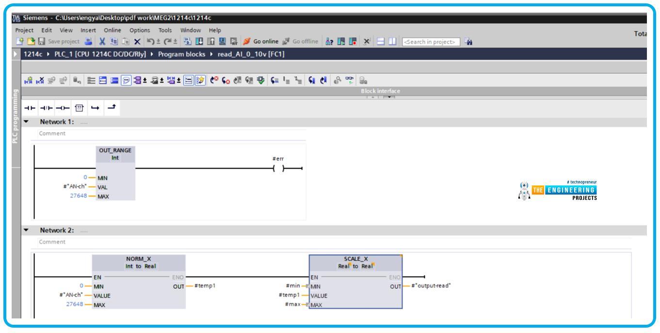
Let us give another example but in siemens s7-1200 which is represented by Fig. 5. The ladder code is very simple and it consists of two runs as shown in fig. 5; the first one is for validating the reading to be within the range which is from 0 to 27648 and the second rung is the main one which performs the analog processing in two steps. Firstly it normalizes the input based on the aforementioned range and then it scales the output back to represent it in the output signal format. In this example, we measure a battery voltage that is typically located in the range of 0 to 12v. Therefore, the min and max parameters in the scale_X block should be 0 and 12 v respectively.
Fig. 5: Example of processing analog inputs in Siemens S7-1200
Figure 6 demonstrates the test of the analog processing showing the output reported 5.858941 when the reading was 13499 which is high accuracy.
Fig. 6: Simulation of processing analog inputs in Siemens S7-1200
What’s next
I am truly thrilled to have you shared with me such a very important tutorial about analog input processing and scaling with parameters because this is a very common operation you might see in every operation in the industry as there are hundreds of sensors that read analog physical signals and be processed by the controller for deciding the next stage of the operation. Next time we are going to talk about jumping and branching techniques in the ladder logic program. So please be ready to meet very soon and learn together and enjoy practicing plc ladder programming
JLCPCB – Prototype 10 PCBs for $2 (For Any Color)
China’s Largest PCB Prototype Enterprise, 600,000+ Customers & 10,000+ Online Orders Daily
How to Get PCB Cash Coupon from JLCPCB: https://bit.ly/2GMCH9w
The post Analog Input Scaling in Ladder Logic Programming appeared first on The Engineering Projects.


No comments:
Post a Comment