
 Hey Pals! we are desired and pleasant to see you in The Engineering Projects. We hope you are doing Great. We have started a series about the Logical Circuits and experiments. In this session, we’ll seek the answers of the following questions:
- What are Half subtrators?
- What is the working Mechanism of Half Subtractor?
- How can we design the Truth table of Half Subtractor?
- How can We implement the Half Subtractor in Proteus ISIS using three Logic Gates?
- How can we use the NOR Gate to implement the Half Subtractor in Proteus ISIS?
You’ll Learn some simple but useful concepts about the Half Subtrators in DID YOU KNOW section into the bargain.
Half Subtrator
The subtrators belongs to the domain of electronics and we define the subtrators as:
“Half Subtractors are bi-input and bi-output Logical Devices that are specially designed to Get the Binary digits, Subtract them and show the Difference and the Carry through output devices.”
The subtractors are considered as one of the building blocks of many Electronic Devices.
The inputs are usually named as A and B and the outputs are called the Difference and Borrow.
DID YOU KNOW????????????
Subtractors are the Electrical Circuits that Perform the subtraction of Numbers and bits in the computer.
Working Mechanism of Half Subtractor
The Half Subtractor has a boolean circuit. It means it works only with the two digits i.e, 0 and 1. The 0 describes the LOW bit and vise versa. It take two bits through the input Terminals and calculate the whole system then shows us the result at the Output Terminals.
Difference in Half Subtractor
The difference is obtained when we perform the minus operation with the second bit from the first bit. the calculator give us the output that is the remaining value of the 1st bit when we deduct the value of 2nd bit from it.
Borrow in Half Subtractor
In the case, when the second bit is higher then the 1st bit, the subtractor borrows a bit from the circuit. this is an essential operation because without this, subtraction can not be proceed further.
Half Subtractor Truth Table
In binary digit difference, the subtraction of 0 with 0 produces the difference 0 and the borrow 0. when the Value is change to A=0 and B=1 then the circuit borrows a bit and both the bits becomes 1 hence we get Difference=1 and borrow=1.
When the inputs are A=1 and B=0 then we simply get the value Difference=1 and Borrow=0. At the same token, when A=1, B=1 then the result we get is Difference=0, Borrow=0.
Using all these concepts we get the Truth Table as:
| A | B | Difference | Borrow |
| 0 | 0 | 0 | 0 |
| 0 | 1 | 1 | 1 |
| 1 | 0 | 1 | 0 |
| 1 | 1 | 0 | 0 |
In this tutorial we’ll learn to design Half subtractor in two ways:
- Half Subtractor using three Logic Gates.
- Half Subtractor using only NAND Gate.
DID YOU KNOW???????????
Half subtractors are used to limit the force of audio or Radio signals.
Half Subtractor Using three Logic Gates
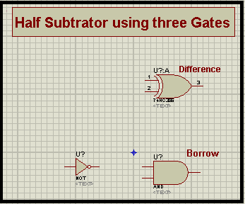
In this type of formation we use three Logic Gate given below:
- XOR Gate
- NOT Gate
- NAND Gate
When we look at the working of the Half Subtrator, we’ll find that the working of the Difference mode of the Half Subtractor is same as the XOR Gate because we that that XOR Gate is the one that gives the output HIGH only when the inputs have different values from each other and vise versa. Just have a look at its Truth Table:
| A | B | A XOR B |
| 0 | 0 | 0 |
| 0 | 1 | 1 |
| 1 | 0 | 1 |
| 1 | 1 | 0 |
Therefore, we simple use the XOR Gat for the function of Difference.
When we look at the Function of Difference. we use one AND Gate. A NOT Gate is attached with the one of the input of AND Gate. One may wonder, why we are using the two Gate when we can use the NAND Gate. but the point is, we just need the inverse condition of just one input. Therefore we use this arrangement.
Proteus simulation for Half Subtractor sing Three Gates
Material Required
- XOR Gate
- AND Gate
- NOT Gate
- LED-RED
- Ground Terminal
- Connecting Wires
DID YOU KNOW?????????????
Arithmatic Logic Unit uses the Half Subtractor for the functioning.
- Begin you Proteus Software.
- Choose first four Components from Pick Library through “P” Button.
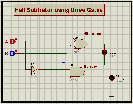
- Arrange the Logic Gates one after the other one the working area just as shown in the image:
- Arrange two Logic Toggles Just in front of the XOR Gate.
- Get one LED and Set it Just after the XOR Gate.
- Repeat the step with the with AND Gate.
- Go to Terminal Mode>Ground attach a ground Terminal with each LED.
DID YOU KNOW?????????????????
One can also use the Logic Probe to Get the output instead of LED.
- Connect all the Components through wires in accordance with the image below:
- Change the values at the Input one after the other and notice the output.
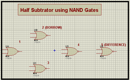
Half Subtrator using NOR Gate
Sometimes, you need to make the Circuit as simple as you can. Or you can only use one gate then it is also possible to make the whole circuit using just one gate i.e, NOR Gate.
when we look at the definition, it says A NOR Gate is the one that shows the output HIGH only when the Input are LOW. So, one can use the NOR Gate in different ways just by using the connection in a specific way.
Let’s see how can we do this.
Proteus Simulation of Half Subtractor using NOR Gate
Material Required
- NOR Gate
- Logic Toggle
- LED-RED
- Ground Terminal
- Connecting Wire
- Choose the Required Material.
- Arrange the NOR Gates with respect to the image given next:
- Set Logic Toggles in front of Gate 1.
- Attach the LED’s with the output of Gate two and 5.
- Ground each LED.
- Join all the devices through Connecting wires with the help of this image:
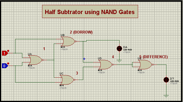
You will Observe that this circuit works as the half subtrators when you will change the Value of Logic Toggles.
Thus today we Learned what are Half Subtrator, How does the Truth table of Half Subtractor is designed, How can we design the Circuit of Half Subtractor with three Gates as well as using just a NOR Gate.
If you want to learn more, you can visit the site for other tutorials as well.
JLCPCB – Prototype 10 PCBs for $2 (For Any Color)
China’s Largest PCB Prototype Enterprise, 600,000+ Customers & 10,000+ Online Orders Daily
How to Get PCB Cash Coupon from JLCPCB: https://bit.ly/2GMCH9w
The post Half Subtractor in Proteus ISIS appeared first on The Engineering Projects.
No comments:
Post a Comment