
 Hello friends, I hope you all are having fun. In today’s tutorial, we will have a look at Series Clippers & its types in Proteus. In this article, we will learn all the basic things about the series clippers. Today, We are going to learn:
- What is clipper
- What are types of clippers
- Implementation of series clippers in Proteus
lets rush toward the 1st Question.
What is clipper ???
- Clipper (also known as Limiter) is an electronic circuit, which clips or limits the amplitude (either positive, negative or both) of AC source wave.
- Diodes are normally used for designing Clippers and such circuits are normally referred as Diode Clipping Circuits (Diode Limiting Circuits).
- Here’s an example of a Diode Clipping Circuit, where we are clipping the positive amplitude of AC pulse:
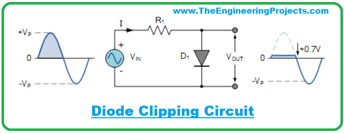
- As you can see in above figure,we are clipping the positive side but if we want to clip the negative side then we just need to reverse the polarity of diode.
- Clippers are normally used for protection purposes i.e. if there’s some voltage spikes then clip it to secure home appliances.
- Half wave Rectifier is also a type of clipper as its clipping one side of AC pulse to 0V.
Now, let’s have a look at different types of clippers:
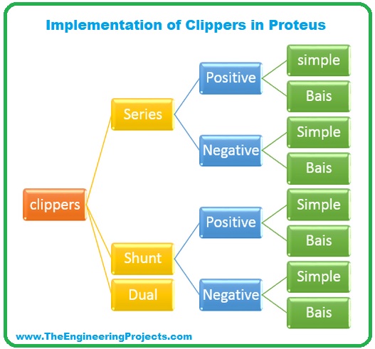
Types of Clippers
- Series Clippers.
- Positive.
- Positive with bias.
- Negative.
- Negative with bias.
- Shunt Clippers.
- Positive.
- Positive with bias.
- Negative.
- Negative with bias.
- Dual (Combination) Clippers.
As today’s topic is about Series Clippers, so let’s implement them in Proteus ISIS:
Implementation of Series Clippers in Proteus ISIS:
- In the first place, start your Proteus software. I am using Proteus 7 ISIS.
- Choose the components from “Pick ” library present in the left side of screen.
- For this experiment, we need:
- Diode
- Resistor
- Vsine source
- battery
- Different arrangements are used in different types of clippers. but two things will remain same. hence I am going to set them and showing it to you clearly. Then we will change the arrangements of other components for different types of Clippers.
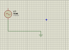
fixed components for clippers
- Here the AC source is Vsine. Double click on the vsine source and change the value of amplitude and frequency to 11V and 1000Hz respectively.
we’ll talk through about types of Series Clippers in proteus one by one.
1. Positive Series Clippers in Proteus ISIS
In Positive Series Clipper, positive half cycle of the wave is clipped i.e, removed. The circuit is said to be the positive clipper circuit, if the arrowhead of the diode points towards the input source.
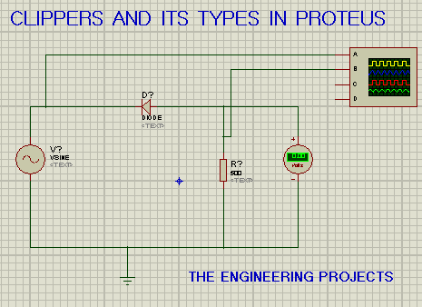
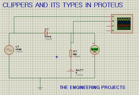
- To make this circuit, we will add the other components according to the requirement. The diode D is connected in series with the load resistor.
- Double click at resistor and change its value from 10k ohm to 500 ohms.
- We’ll also add the DC voltmeter to show the difference between biased and unbiased circuit
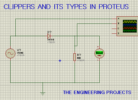
- Connect terminal A after the Vsine source i.e. the alternating current and terminal B of oscilloscope after the diode, as shown in figure below:
- This is the time to pop the play button and set values of oscilloscope according to the table:
|
|
|
|
|
|
|
|
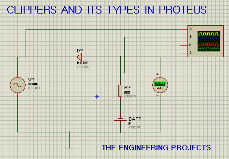
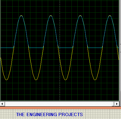
- As soon as we will change the value, we will get the required output as shown in the figure:
We can clearly see that the positive side of the AC source waveform is now clipped because we all know A diode only allows the passage to the half sinusoidal cycle. hence, we get a current in the same direction i.e, Direct current.
2. Positive with Negative Bias in Proteus
A series clippers with negative bias is the one in which diode is pointing towards the current source and is in series with the resistor, and the positive terminal of battery is connected with the negative side of diode and negative side of battery is connected with the positive side of diode.
- In our circuit, we will just add the battery cell with the resistor as shown in figure:
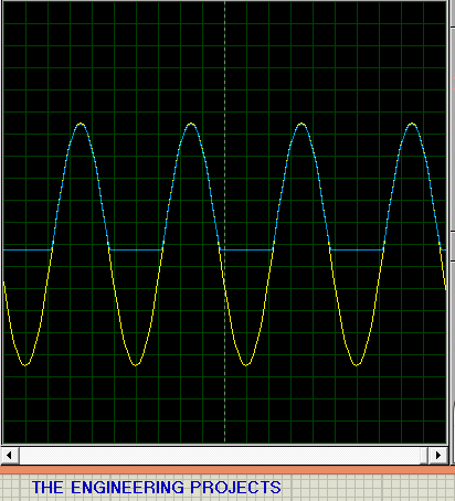
You can distinctly see that the volt meter shows the value of -5V. This 5 volt is the value of battery. The negative sign shows that the circuit is negative bias.
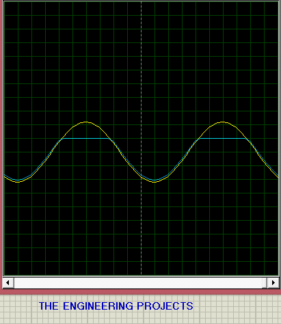
- The output for the circuit on oscilloscope is given as:
NOTE: If you want a clippers with positive bias, simple change the direction of the battery. Connect negative terminal of battery with negative side of diode and the same is for positive side.
3. Negative Series Clipper in Proteus
For this type, negative half cycle of the wave is clipped i.e, removed. The circuit is said to be the negative clipper circuit if the arrowhead of the diode points towards the load resistor then it is called series negative clippers.
- To make this circuit, We will add diode and other components such that the arrowhead of the diode is pointing against the Vsine source and the diode D is connected in series with the load resistor.
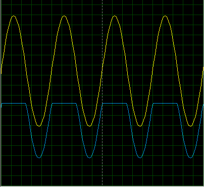
- Similarly, the output of oscilloscope for the series circuit of negative clippers shows us that the negative side of the wave is clipped:
4.Negative with negative bias
By the same token, we call the Circuit as series clippers with negative bias if
- The diode is pointing opposite to the direction of the sinusoidal wave source
- Is in series with the resistor
- We will connect negative terminal of battery with the positive side of diode
- Connect positive side of battery with the negative side of diode.
- so, in our circuit, we will just add the battery cell with the resistor as shown in figure:
- When we play this circuit the oscilloscope shows the output as:
So learners, how was the experiment? Did you get the best output?
In this article learnt about clipper as well as its types and our focus was on series clippers. Moreover, for more types of Clippers you can see Shunt clippers and dual clippers in proteus.
The post Series Clippers and its types in Proteus appeared first on The Engineering Projects.
No comments:
Post a Comment