 Hi Guys! Happy to see you here. Thank you for viewing this read. In this post today, I’ll walk you through the complete Introduction to BC550. BC550 is a low power low-frequency general-purpose bipolar transistor. It is mainly used to drive loads under 100mA. BC550 carries three terminals where small current across one terminal is used to control the large current across remaining terminals. It’s primarily used for amplification and switching purposes. Transistors are critical components and building blocks of modern electronic circuits. Bipolar junction transistors are divided into two main types named NPN transistor and PNP transistor. The BC550 falls under the category of NPN transistors and is available in a plastic TO-92 case. I suggest you read this entire post all the way through as you’ll get to know all nitty-gritty of BC550 i.e. datasheet, pinout, working principle, power ratings, applications, and physical dimensions.
Keep reading.
Introduction to BC550
- BC550 is an NPN bipolar junction transistor mainly used for switching and amplification purpose.
- It incorporates three pins called the emitter, base, and collector. Where small current change at the base terminal is used to induce large current change across other terminals.
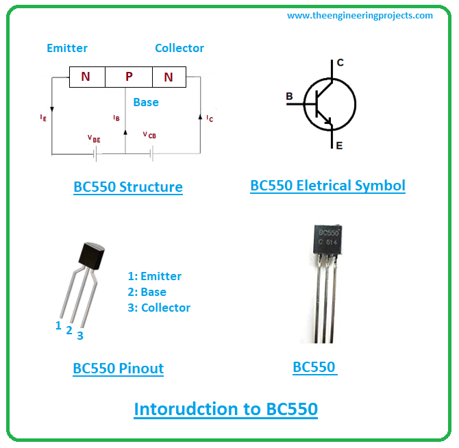
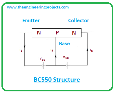
- BC550 carries three layers i.e. two N-doped layers and one P-doped layer. The P-doped layer indicates a positively charged layer that stands between the two N-doped layers that are negatively charged.
- When this transistor acts as a switch it is used to turn ON and OFF the input signal. When a powerful signal passes through the transistor, it turns ON the switch while lack of signal turns the switch OFF.
- When several thousands of millions of transistors are formed together, they can be incorporated into integrated circuits or in discrete components.
- BC550 is composed of semiconductor material. Silicon is mostly used to form these NPN transistors.
- In this NPN transistor, electrons are majority carriers used for conductivity as opposed to PNP transistors where conductivity is carried out with holes as majority carriers.
- It is important to note that the movement of electrons is far better and faster than the movement of holes, the reason NPN transistors are better, thus preferred over PNP transistors.
- The main difference between NPN and PNP transistors is the behavior of the base terminal. In NPN transistors, current flows through the base terminal while in the case of PNP transistor no current flows through the base terminal when a transistor is ON.
- Also, the current flows from collector to emitter in NPN transistors, and in PNP transistors current flows from emitter to collector.
- Computer circuit boards are the common example of NPN transistors that carry millions of transistors used to store memory in the form of binary code.
BC550 Datasheet
- To understand the component thoroughly, it’s always wise to scan the datasheet.
- You can download BC550 Datasheet by clicking the button below:
BC550 Pinout
BC550 comes with three pins called
1: Emitter
2: Base
3: Collector
The following figure shows the pinout of the BC550.
- All these terminals are different in terms of their doping and functions.
- Emitter terminal is highly doped compared to the other two terminals.
- The emitter emits the electron into the base terminal which controls the number of electrons. The collector terminal is used to collect the number of electrons.
BC550 Pin Configuration
BC550 can be embedded in the following three configurations:
1: Common emitter configuration
2: Common collector configuration
3: Common base configuration
- Mostly amplification is carried out using common emitter configuration as it comes with the exact voltage and current ratings required for amplification purposes.
- The amplification factor is an important factor used to define the nature of amplification. It’s a ratio between collector current and base current and is denoted by β.
- The current gain is another factor which is a ratio between collector current and emitter current. It is denoted by α and is known as alpha. The alpha value ranges from 0.95 to 0.99 but mostly its value is taken as unity.
BC550 Working Principle
- In BC550, the base works as an electron valve that controls the number of electrons. When a voltage is applied across the base terminal, it triggers the electron reaction. Thus, emitter starts emitting the electrons into the base terminal which are then collected by the collector.
- A small change in input voltage at the base terminal produces a large change in output voltage across other terminals. This phenomenon is used for amplification purposes.
- The collector voltage is always positive with respect to the emitter terminal while the base terminal is positive with respect to the emitter.
- And the collector terminal is combined to the load voltage using a resistor which is used to control the flow of current.
BC550 Power Ratings
The following table shows the absolute maximum ratings of BC550.
| Absolute Maximum Ratings BC639 | ||||
|---|---|---|---|---|
| No. | Rating | Symbol | Value | Unit |
| 1 | Collector-Emitter Voltage | Vce | 45 | V |
| 2 | Collector-Base Voltage | Vcb | 50 | V |
| 3 | Emitter-Base Voltage | Veb | 5 | V |
| 4 | Collector Current | Ic | 100 | mA |
| 5 | Collector Power Dissipation | Pc | 500 | mW |
| 6 | Junction Temperature | Tj | 150 | ºC |
| 7 | Storage Temperature | Tstg | -55 to 150 | ºC |
- Emitter-Base voltage is 5V, which means the only 5V is required to trigger the base terminal, thus the entire transistor. While Collector-Base and Collector-Emitter voltages are 50V and 45V respectively.
- The collector current is 100mA i.e. it can drive loads with a value under 100mA.
- It’s wise to do your due diligence before incorporating this tiny device into your project as values exceeding absolute maximum ratings can severely damage the component.
- Plus, make sure you don’t apply these values for more than the required time, else they can affect the device reliability.
BC550 Alternatives
BC550 equivalent are:
The complementary PNP transistor of the BC550 is BC560.
BC550 Applications
- Used for amplification and switching purposes.
- Can be employed in the current mirror and H-bridge circuits.
- Used in linear amplifier and impedance buffering.
- Finds applications in oscillator and comparator circuits.
- Used in Astable and Bistable multivibrator circuits.
- Used for pre-amplification stages in electronic circuits.
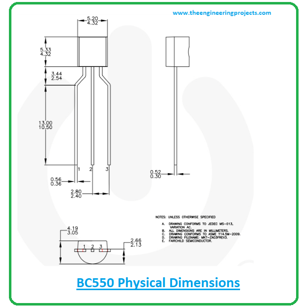
BC550 Physical dimensions
The following figure shows the physical dimensions of the BC550.
That’s all for today. Hope you’ve got a clear insight into the Introduction to BC550. You’re most welcome to ask your queries in the section below. I’d love to help you the best way I can. Feel free to keep us updated with your valuable suggestions and feedback. Thank you for reading this post.
JLCPCB – Prototype 10 PCBs for $2 (For Any Color)
China’s Largest PCB Prototype Enterprise, 600,000+ Customers & 10,000+ Online Orders Daily
How to Get PCB Cash Coupon from JLCPCB: https://bit.ly/2GMCH9w
The post Introduction to BC550 appeared first on The Engineering Projects.


No comments:
Post a Comment